


Next: Integration of the Rigid
Up: Rigid Bodies and Rotational
Previous: Rigid Bodies and Rotational
Contents
Index
A rigid body unit is a collection of point atoms whose local geometry
is time invariant. One way to enforce this in a simulation is to
impose a sufficient number of bond constraints between the atoms in
the unit. However, in many cases this is may be either problematic or
impossible. Examples in which it is impossible to specify sufficient
bond constraints are
- linear molecules with more than 2 atoms (e.g. CO
 )
)
- planar molecules with more than three atoms (e.g. benzene).
Even when the structure can be defined by bond constraints the
network of bonds produced may be problematic. Normally, they make the
iterative SHAKE procedure slow, particularly if a ring of constraints
is involved (as occurs when one defines water as a constrained
triangle). It is also possible, inadvertently, to over constrain a
molecule (e.g. by defining a methane tetrahedron to have 10 rather
than 9 bond constraints) in which case the SHAKE procedure will become
unstable. In addition, massless sites (e.g. charge sites) cannot be
included in a simple constraint approach making modelling with
potentials such as TIP4P water impossible. All these problems may be
circumvented by defining rigid body units in terms of a center of mass
(c.o.m) and an orientation and solving the resultant rigid
body equations of motion. 2.5
A rigid body has associated with it a rotational inertia matrix
 , whose components are given by
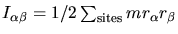 where the
  are the
distance to the centre of mass and the
are the
distance to the centre of mass and the  are the site masses. In DL_POLY_2
we define the local body frame to be that in which the rotational
inertia tensor
are the site masses. In DL_POLY_2
we define the local body frame to be that in which the rotational
inertia tensor
 is diagonal and the components satisfy
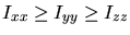 . These three components are stored in
the arrays rotinx, rotiny and rotinz for each unique
type of rigid body in the system. The total mass of the rigid body
unit,
. These three components are stored in
the arrays rotinx, rotiny and rotinz for each unique
type of rigid body in the system. The total mass of the rigid body
unit,  , is stored in the array gmass and the location of
sites with respect to the local body axes are stored in the arrays
gxx, gyy and gzz.
, is stored in the array gmass and the location of
sites with respect to the local body axes are stored in the arrays
gxx, gyy and gzz.
The orientation of a local body frame with respect to the space fixed
frame is described via a four dimensional unit vector, the quaternion
![$\mbox{$\underline{q}$} = [q_0,q_1,q_2,q_3]^T$](img557.png) . The Rotational matrix to transform
from the local body frame to the space fixed frame is the unitary
matrix
. The Rotational matrix to transform
from the local body frame to the space fixed frame is the unitary
matrix
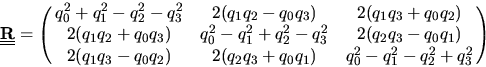 |
(2.202) |
so that if
 is the position of a site in the
local body frame with respect to its centre of mass, its position in
the space fixed frame (w.r.t. its centre of mass) is given by
is the position of a site in the
local body frame with respect to its centre of mass, its position in
the space fixed frame (w.r.t. its centre of mass) is given by
 |
(2.203) |
Next: Integration of the Rigid
Up: Rigid Bodies and Rotational
Previous: Rigid Bodies and Rotational
Contents
Index
W Smith
2003-05-12